Usměrňovací můstek
Usměrňovací můstek je elektrické zařízení, soustava čtyř a více diod v můstkovém obvodu, které vytváří výstup stejné polarity pro jakoukoliv polaritu vstupu. V nejběžnější aplikaci se můstkové usměrňovače používají k převádění střídavého proudu na stejnosměrný proud.
Můstkový usměrňovač byl vynalezen polským elektrotechnikem Karlem Pollakem, který si jej patentoval v prosinci 1895 ve Velké Británii a v lednu 1896 v Německu.[1] V roce 1897 nezávisle objevil a publikoval Leo Graetz podobné zapojení. Dnes je diodový můstek často označován jako Graetzův obvod či Graetzův můstek.
Jednofázový můstek


Jednofázový můstek využívá spojení čtyř diod, z nichž v každé půlvlně vedou dvě diody. Velikost usměrněného napětí (zanedbá-li se úbytek napětí na diodách) je dána vzorcem:[2]
kde:
- UDC – střední hodnota výstupního napětí
- UAC – efektivní hodnota vstupního napětí
Třífázový můstek


Třífázový můstek využívá spojení šesti diod, z nichž v každém okamžiku vedou dvě. Velikost usměrněného napětí (zanedbá-li se úbytek napětí na diodách) je dána vzorcem:[3]
kde:
- UDC – střední hodnota výstupního napětí
- UAC – efektivní hodnota sdruženého vstupního napětí
Galerie
 Diodový můstek z diskrétních součástek
 Integrovaný diodový můstek 1000VX4A
 Různé můstky
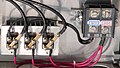 Výkonový diodový usměrňovač s chladičem
Odkazy
Reference
- ↑ Britský patent 24398 (německy)
- ↑ KŮS, Václav. Elektrické pohony a výkonová elektronika. Plzeň: Západočeská univerzita v Plzni, 2005. ISBN 80-7043-422-8.
- ↑ KOLÁŘ, Václav; VRÁNA, Václav. ZÁKLADY POLOVODIČOVÉ TECHNIKY [online]. Fakulta elektrotechniky a informatiky VŠB-TUO [cit. 2024-01-23]. Dostupné online.
Externí odkazy
 Obrázky, zvuky či videa k tématu usměrňovací můstek na Wikimedia Commons
 - Power Supplies[nedostupný zdroj] (anglicky)
Média použitá na této stránce
Diagram of a fully rectified 50 Hz sine wave. The RMS effective value is indicated.
Autor: Zureks, Licence: CC BY-SA 3.0
Output voltage waveform of a three-phase full-wave rectifier.

Autor: Mercado Viagens from Brasil, Licence: CC BY 2.0
A full wave rectifier diode bridge, rated at 4A x 1000 V

Autor: Původně soubor načetl Glogger na projektu Wikipedie v jazyce angličtina, Licence: GPL
"Tridge Rectifier" (three phase bridge rectifier)
This picture shows the tridge rectifier currently in use on the thumb|Lakota rooftop mounted urban wind turbine running in the heart of downtown Toronto, Canada Lakota rooftop mounted wind turbine currently running at 330 Dundas Street West, Toronto, Ontario.
Three phase alternating current comes in the three black wires at the upper left hand corner of the image. These are the three electrical hot wires coming down the center of a size 9 schedule 40 structural tower from the windmill. There is no neutral. There is a ground, which is the metal housing.
Leftmost, bolted to a large heatsink, there are three double diodes.
Three black wires come out the top of each double diode, and three red wires come out the bottom.
The black and red wires go to the screw terminals labelled "negative" and positive" respectively.
The screw terminals are shown rightmost in the picture.
These terminals go to a 12 volt 2000 Amp Hour battery that weighs approximately 2000 pounds, as well as to a 12 volt distribution system in the building to support a community of cyborgs, i.e. to charge 12 volt batteries as well as to run various of the 12 volt equipment that has accumulated from 30 years of wearable computing work. Such equipment includes various communications systems, Internet gateways, and other systems that must keep running regardless of whether or not there is a power failure.
This system, having separate turbine and rectifier, replaces an earlier dilapidated wind power system that was based on an automotive alternator with six diodes built into it. With the earlier system it was necessary to "hack" the circuit in order to get three phase power out of it because automobile alternators do not normally provide three phase power directly to the outside terminals.
The new system is preferable for teaching use, because the rectifier is located inside the building, allowing maintenance and research to be carried out without climbing up the mast (e.g. to change diodes, etc., which required climbing up the mast and taking down the alternator with the old system).
Autor: MarBar SK, Licence: CC BY-SA 4.0
Ručne zospájkovaný diodový mostík zložený zo 4. diód.
Farebný kód drôtikov: •Žltý - Vstup striedavého napätia (zvyčajne z transformátora). Sú tu dva drôtiky totožnej farby - pretože diodový mostík je bipolárny... •Červený - kopčekové* jednosmerné napätie + •Modrý - kopčekové* jednosmerné napätie -
- kopčekové jednosmerné napätie - keď chceme mať na osciloskope rovnú čiaru (pravé jednosmerné napätie) tak potrebujeme za mostík pripojiť kondenzátor. Keď tak nespravíme tak jednosmerné napätie bude kopčekové a vypadá nejako takto: akokeby sme sme skombinovali dve matematické funkcie- sínus a inverzný sínus (sínus s fázovým posunom o π) ale s tým, že odignorujeme všetko záporné alebo zápornú časť proste nevykreslíme...
New diode bridge diagram (animated)

Autor: Smial na projektu Wikipedie v jazyce němčina, Licence: CC BY-SA 2.0 de
Bridge rectifiers of various designs, including a selenium rectifier in a flat package (bottom left, 30V, 300mA) and a model for the connector receptacles.
Autor: Sonarpulse, Licence: CC BY-SA 3.0
tri-phase bridge rectifier schematic